Download

1 / 17
170 likes | 355 Views
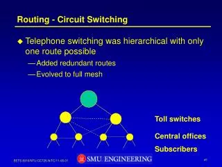
Repeating. Repeating. Repeating. Repeating. Repeating, Bridging, Switching, and Routing. Home Visitor 0 63. We Deliver For You. Eric L. Michelsen. Topics. Simple Ethernet LAN Simple Repeating Repeated Repeaters Multiport Coax Repeaters Bridging

E N D
Repeating Repeating Repeating Repeating Repeating, Bridging,Switching, and Routing Home Visitor 0 63 We Deliver For You Eric L. Michelsen
Topics • Simple Ethernet LAN • Simple Repeating • Repeated Repeaters • Multiport Coax Repeaters • Bridging • Spanning Tree • Switching • Routing
Where in the Stack? 7. Application 7. Application Application Gateway 6. Presentation 6. Presentation 5. Session 5. Session 4. Transport 4. Transport 3. Network 3. Network Router 2. Link 2. Link Bridge 1. Physical 1. Physical Repeater Note: IP routers used to be called “gateways,” not to be confused with “application gateway.”We won’t be talking about application gateways.
node node node MAC MAC MAC node node MAC MAC Simple Ethernet LAN • Layer 2 interface to host, Layer 1 interface to medium • Each Ethernet interface has globally unique MAC address • Ethernet has restrictions: 10Base5 10Base2 10BaseT 100BaseT • Cable Length 500m 185m 100m 100m • Number of Interfaces100 30 2 2 Layer 2 7. Application · · · 10Base2 (coaxial) 6. Presentation 185 m Layer 1 5. Session 4. Transport 3. Network 2. Link 10BaseT (2-pair UTP) 1. Physical 100 m
Ethernet Services • Local addressing • LAN: Local Area Network • Despite globally unique MAC addresses, nodes can only reach local hosts (hosts on their LAN) • Datagram service • One packet at a time • Best effort delivery • Not guaranteed • No acknowledgement • Other services (reliable delivery, global addressing) require Layer 3 and higher protocols 7. Application 6. Presentation 5. Session 4. Transport 3. Network Local addressing Datagram Best effort 2. Link Raw bits 1. Physical Wires, voltage, current
node node node node node node node node node node node Simple Repeater • Simplest and lowest overall network performance • Repeats everything, including collisions • Transparent to nodes • All interfaces must run at the same speed (no buffering) · · · · · · 10Base2 (coaxial) Repeater Segment 1, 185 m Segment 2, 185 m 370 m Repeating Hub Repeating Hub 100 m 100 m 100 m 10BaseT 10BaseT 100 m 100 m 100 m 100 m
Repeated Repeaters • Repeaters can be chained up to a limit: the 5-4-3 rule:Between any 2 nodes, no more than • 5 segments • 4 repeaters • 3 coax segments • Fun fact: 4-3-4 is also allowed (802.3 sec 13.3.f.3) non-coax non-coax Repeater Repeater Repeater Repeater 10BaseT Repeating Hub Repeating Hub Repeating Hub Repeating Hub
Multiport Coax Repeaters • Still follows the 5-4-3 rule • With all repeaters, broadcast domain and collision domain are the same non-coax non-coax Repeater Repeater Repeater Repeater coax Broadcast domain Collision domain
node node node node node node MAC MAC MAC MAC MAC MAC BridgingYours is Yours, and Mines is Mines • Bridges separate traffic as needed by segment • Learn node MAC addresses dynamically (at least 4000) • Flood unknown MAC addresses & broadcasts on all ports • Bridge ports have no MAC addresses (transparent to nodes) • Store and Forward delivery (typically) • Each interface can run at an arbitrary speed (bridges have buffering) • Standardized in IEEE-802.1d • Collision domain is per segment, broadcast domain is all hosts on LAN No MAC Bridge Collision domain Collision domain Simultaneous traffic Broadcast domain
X Disabled by spanning tree. Frames from B to C go through bridge A X Disabled by spanning tree Spanning Tree Protocol (STP) • Bridge loops are catastrophic • Spanning Tree protocol disables redundant links, restores them dynamically as needed • Suboptimal routing: minimum path along spanning tree • Bridge as a whole has a MAC address (not its interfaces) Chosen by spanning tree as root bridge Bridge MAC Bridge A MAC node node Unknown or Broadcast packet crashes network Bridge B MAC Bridge C MAC node node node node Bridge MAC
Switching (3Com Link Switch 1000)A Bridge Too Far • Imagine a big bridge with lots of ports (LS-1000 has 24) • Runs all interfaces simultaneously at (or near) wire speed • Default path for unknown MAC addresses (not flooded) • Broadcasts must still be flooded • Cut through delivery (typically, but configurable) • Optional spanning tree: just don’t do it Default Path Switching Hub Simultaneous traffic Broadcast domain Collision domains
Bridge/Switch Fun Facts • Addresses age out after configurable time • default 5 minutes on 802.1d bridge • default 15 minutes on LS-1000 • Lost address is more severe on a switch (no flooding) • 802.1d bridge learns 4000 addresses, LS-1000 learns 500 • No flow control (typically), discard overflow • LS-1000 can invoke flow control by deliberately colliding with inbound frames it cannot handle • LS-1000 has 3 forwarding modes: • Cut Through: as fast as possible (propagates some collisions) • Fragment-Free: cut through after collision time over (512 bits, propagates CRC errors) • Store-and-Forward: maximum delay, forwards only good frames
Wireless LAN • Unlicensed National Information Infrastructure (U-NII) band, which spans 5.15 to 5.35 GHz and 5.725 to 5.825 GHz. The lower 200 MHz of the band is used for in-building applications; the upper 100 MHz is typically used for building-to-building or campus-bridging systems. • ISM bands (Industrial, Scientific and Medical) • 2.4 to 2.483 GHz, 802.11 specifies a total of 79 channels with 1-MHz spacing. data rates of 1, 2, 5.5, and 11 Mbps
RoutingA Cut Above • Routing operates completely at Layer 3 (e.g., IP) • repeating, bridging, switching are Layer 1/2 (e.g., Ethernet) • Routing has nothing to do with Ethernet, FDDI, Token Ring, etc. • Each packet takes one route: no flooding • Routing protocols update topology • Arbitrary topology: loops allowed 7. Application Frame Relay Router Router Nodes Nodes 6. Presentation 5. Session SONET ATM 4. Transport 3. Network Router Router Nodes Nodes Telephone modem 2. Link 1. Physical
Routing: The Whole Truth • Routers find least cost path • Time To Live (TTL) kills looping packets • Default routes minimize routing table size • Each Layer 3 protocol requires 1 or more routing protocols • IP uses RIP, RIP2, OSPF, EGP, GGP, ... • IPX uses IPX RIP (not IP RIP) • Opaque to nodes: they must interact with routers • IP uses ICMP • IPX nodes listen to RIP Router 1 Router 2 node A node B Least cost path Router 3
Side By Side Repeating Bridging Switching Routing Works at Layer... 1 2 2 3 Transparent? Yes Yes Yes No Performance worst ok high high delay Complexity low medium high way-high Topology restricted,no loops arbitrary no loops arbitrary Packet Flooding always broadcast &unknown broadcast (w/ default route) never Looping packet catastrophic catastrophic catastrophic TTL kills it Unknown address flood flood or opt. discard default default ordiscard Forwarding instant store & fwd cut thru (typ) store & fwd Topology learning none STP opt. STP L3 protocol