Download
1 / 14
140 likes | 254 Views
In order to show our commitment with the telecommunication field and people who works or is looking forward to work at it, Beyondtech decided to launch a series of publications related with optical fiber technical procedures, to help apprentices and aficionados to improve their techniques and learn everything they can about this amazing topic.<br><br>This first publication describes the procedures you need to follow to do optical fiber terminations, meaning connectorizations and mechanical splices, with detailed steps and tips.<br> <br>More publications are yet to come, from guides and manuals to papers about optical fiber basics and its applications in several fields. We are working for you. Be aware!

E N D
Introduction Optical fiber terminations need to be done carefully in order to have low loss and minimal reflectance, therefore constant practice is mandatory to achieve perfection. This E-book is created for optical fiber apprentices eager to exercise and improve their techniques. Part I details the steps to be followed to do a permanent joint using a mechanical splice, Part II explains how to do a connectorization and Part III describes the way polishing needs to be done. This processes might be used with both multimode and single-mode optical fiber and with other connectors besides ST. Always remember to use safety goggles to avoid optical fiber fragments to get into your eyes. Let’s start practicing! Beyondtech, inc Beyondtech, inc Beyondtech, inc Beyondtech, inc
Is the process of precisely aligning two fiber optics together using an alignment device and index matching gel, with refractive index similar to the fibers’ and covers possible air gaps, helping light travel from one fiber to another with minimal loss and little back reflection. MECHANICAL SPLICING However, they are still two separate optical fibers, which is why this method is con- sidered temporary and is mostly use to rapidly restore short-haul single mode or multimode cables in FTTH installations. How to do it? Mechanical splicing is easy to do if you have all the tools you need, as it only takes three steps to be done. It requires: A fiber optic stripper A cleaver Kimwipes Isopropyl alcohol The mechanical splice device of your need STEP #1 STEP #2 STEP #3 The first thing you have to do is strip the fibers, taking away the coats, buf- fers and protective layers, leaving the optical fibers naked. Then, clean the fiber using an optic clean wipe with isopropyl alcohol. Now it’s time to cleave the fiber. You have to do this following your cleaver’s instructions. And clean the fiber using an optic clean wipe moisturized with isopropyl alcohol. Place the cleaved ends of the fibers together into the mechanical splice device. Now light will travel from one fiber to another thanks to the index matching gel. And your fiber splicing is done! http://beyondtech.us 04
Constantly clean your tools: Particles that you might consider invisible can cause great damages on fiber optics. So getting obsessed with cleaning is never a problem. Invest in a good quality cleaver: Cleaving is the most important step when splicing because a bad cleaves can increase signal loss. Economic cleavers generally need more practice and skills to achieve the appropriate cleave angle, so if you regularly do mechanical splices buy a cleaver that is generally used in fusion splices. If you want to check the signal loss, you could use a Visual Fault Locator, an inexpensive small device that shoots red laser light into the patch cords and makes high loss points visible. This method works great with yellow coated single mode and orange coated multimode fibers. http://beyondtech.us 05
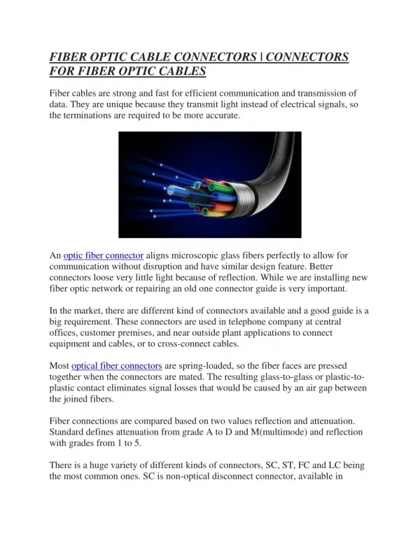
Connectorization is the process of adding a connector at the end of an optical fi- ber cable so it can be temporary joined with another cable or connected to net- work equipment such as receivers, transmitters or patch panels and be quickly disconnected when required. Optical fiber connectors guarantee that fibers are properly aligned, ensuring steady connections. ST, SC, FC and LC connectors can be terminated with similar processes for both multimode and single mode fiber. FIBER OPTIC CONNECTORIZATION How to do it? Before starting, make sure you have all the tools you’ll need and organize them in a comfortable way for you to work. The tools are: The fiber to be terminated The fiber optic connector of your need Epoxy Epoxy syringe Crimp tool Fiber optic scribe Kevlar cutting scissors Alcohol pads Stripper Ruler Marker Kimwipes STEP #1 STEP #2 Mark 0.60 inches on the buffer (mea- suring from the end of the jacket) and continue to use the stripper to remove the exceeding buffer. You might want to do this by cutting the buffer in three sections to avoid scratching the optical fiber. Use a Kimwipe moisturized with isopropyl alcohol to carefully clean the bare fiber, removing any buffer leftovers. Slide the strain-relief boot onto the end of the fiber cable, followed by the crimp sleeve. You can use a piece of tape to keep them in place. Use the ruler and the marker to mea- sure and mark 1.3 inches from the end of the fiber and proceed to remove that amount of jacket using your stripping tool. Now cut the aramid threads using the Kevlar scissors, but be careful to preserve between 0.20 or 0.40 inches of them. http://beyondtech.us 07
STEP #3 STEP #4 STEP #5 Bring the crimp sleeve to the back of the connector. Use the proper crimp tool to crimp the part of the sleeve that covers the connector body and the one that covers the jacket. Slide up the boot so its shelters the con- nector body. And it is done! Put the epoxy into the syringe and remove air bubbles. Place the needle as far as it can go into the connector and push the plunger until you see epoxy coming out the ferrule top, being careful not to let any epoxy come out the bottom. Gently push the optical fiber into the connector and carefully rotate the connector back and forth until its back reaches the Kevlar threads and the jacket end. You really need to do this gently in order to avoid scratching the fiber. http://beyondtech.us 08
Fast terminations: Cyanoacrylates Adhesives: Fisher assures they are used in optical fi- bers although they don’t adhere well to glass. The recommendation is to use these instants adhesives in con- nectors that can later be replaced for epoxy cured connectors. ronments is not as great as epoxy’s. When working with an anaerobic adhesive, replace Step 3 by inject- ing the adhesive into the ferrule, dip the bare fiber in the accelerator bottle and insert it into the connec- tor. It will cure in about 1 minute. FOA recommends using the adhesive Loctite 648 and the ac- celerators Loctite 7471 or 7649. Now it’s time to wait for the epoxy to cure and start polishing. But what if you don’t have time to wait over- night? You are probably thinking you can use a fast room temperature cured epoxy or put the connectors in an oven to accelerate the process. And what happens if you have to do a really quick termination to replace a few damaged connectors at the field or in a premises network? If you are using a cyanoacrylate adhesive, replace Step 3 and do this: Inject the adhesive into the connec- tor, place the cable inside and spray the tip of the ferrule with an acceler- ator. The curing process will be done between 30 seconds and 1 minute. Before deciding if working with adhesives instead of epoxies, keep in mind that epoxy terminated connec- tors have a better performance and reliability. FOA advises to use epoxy because it makes polishing easier since the hardened epoxy at the fer- rule tip protects the fiber from get- ting scratched. Edward A.Y. Fisher, Application Engi- neering Manager, says there are two kind of adhesives you can use in this cases: cyanoacrylates and anaero- bics. Anaerobic adhesives: These are sub- stances that harden when they are set in the ferrule due to the absence of air. Resistance to extreme envi- http://beyondtech.us 09
Polishing is the process that follows connectorization and consists on cleaving and rubbing the protruding fiber to create a smooth surface, in order to avoid high loss and reflectance. It needs to be done carefully to not damage or break the optical fiber. Singlemode optical fiber polishing needs to be done more carefully than mul- timode due to the difference between the diameters of the cores, which makes tiny scratches worst on singlemode connectors. Singlemode fibers are polished with diamond films, while multimode with alumina films. FIBER OPTIC POLISHING How to do it? It is recommended to work on a dark mat .....because it helps you see the fiber. Remember .....to organize your work place in a comfortable .....way be- fore starting. You’ll need: Optical fiber scribe Fiber polishing plate Rubber polishing pad 5µm, 3µm and 1µm lapping films for ceramic ferrules The polishing puck that suits your connector Lint-free wipes Distilled water Isopropyl alcohol Compressed air 200X Microscope *Keep in mind that although some of these steps are repetitious it is necessary to follow all of them to get a proper polish. STEP #2 Air polish the protruding fiber with the 5µm lapping film. Grab the connector steady and gently rub the lapping film back and forth against it for about 20 seconds, until the fiber is leveled with the epoxy bead.Clean the glass polishing plate with a lint- free wipe humidified with isopropyl alcohol. STEP #1 Hold the connector, grab the scribe and score the fiber above the epoxy bead without using too much pressure. Use your thumb and fore- finger to grab the fiber and pull it up and away. Put the fiber in a dispos- al unit. Use an eye loupe to look at the cleaved end of the fiber. A cleave is considered optimal if just a fi- ber diameter of fiber protrudes the epoxy drop. http://beyondtech.us 11
STEP #3 STEP #4 STEP #5 Clean the bottom of the polishing puck and the connector ferrule with a lint-free wipe moisturized with iso- propyl alcohol and dry it with canned air. Insert the connector into the polishing puck while holding both of them on the air. Do not place the polishing put on the rubber pad when inserting the connector because you could break the optical fiber. Put the 5µm lapping film on the rubber pad and gently place the assembled polishing puck on the film, taking care not to scratch the fi- ber. Before following this step, make sure the surfaces of the plate and the rubber pad are properly cleaned. If not, clean them with a lint-free cloth moisturized with isopropyl alcohol. Start rubbing the fiber against it in a figure eight pattern without using too much pressure, until the sur- face smooths. The 5µm film can be reused for 8 to 10 connectors. Once you finish polishing, remove the 5µm film. According Association a properly polished fi- ber requires from four to five figures eight. STEP #8 to the Fiber Optic STEP #6 STEP #7 Clean the rubber pad and the shiny face of the 3µm lapping film using a lint-free wipe moisturized with iso- propyl alcohol. Put the 3µm lapping film on the rubber pad with the shiny face down. Clean the rubber pad and the shiny face of the 1µm lapping film using a lint-free wipe moisturized with iso- propyl alcohol. Put the 1µm lapping film on the rubber pad with the shiny face down. Remove the connector from the polishing puck and clean it using a lint-free wipe soaked with isopropyl alcohol. Use the microscope to check if the fiber is leveled with the tip of the ferrule and if it has any scores. If it is the case, repeat Step 6 and Step 7. Add two drops of distilled water on the 3µm lapping film, softly place the connector on it and start polishing the fiber in a figure 8 pattern without using too much pressure, moving the puck to the dry part of the film. Place two drops of distilled wa- ter on the 1µm film, gently put the connector on it and lightly applying pressure. Start polishing the fiber in a figure 8 pattern, moving the puck to the dry part of the film. About 10 to 15 figures eight should be made to get a proper polish. Check the ferrule with a 200X magnification microscope. You need to check that: * The ferrule endface is free of epoxy. * The fiber is a the same level with the end of the ferrule. About 10 to 15 figures eight should be made to get a proper polish. * The fiber core has no heavy scracthes on it. http://beyondtech.us 12
Recommendations: * If you are doing terminations in the field, be sure that your workspace is as clean as possible and practically dust free. * Don’t apply excessive of pressure when air-polishing and polishing because it could break the fiber. * Be extremely careful when cleav- ing the optical fiber with the scribe. A bad cleave could shatter the fiber. * Make sure your lapping films aren’t worn out. Excessively used lapping films could damage the entire pol- ishing process. http://beyondtech.us 13
Editor: Marialmi Rodríguez Co-Editor: Johann Toirac Photography and design: Nichott León Beyondtech, Inc. Beyondtech is an Optical Fiber designer and manufacturer. Our online store has the best service at the lowest prices with fast and free shipping in the U.S. http://beyondtech.us Visit our website for more information about our services and products All rights reserved.